
具体描述
內容簡介
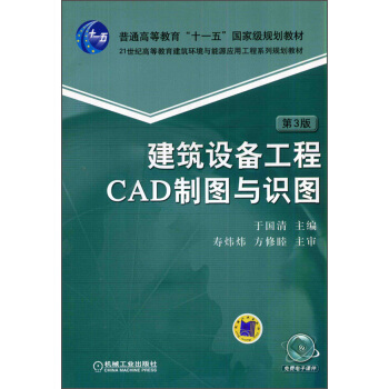
本書依據最新的《房屋建築製圖統一標準》《暖通空調製圖標準》《建築給水排水製圖標準》《供熱工程製圖標準》以及首次頒布的《建築電氣製圖標準》對第2 版的相關內容進行瞭更新。全書係統地介紹瞭暖通空調、建築給水排水、建築電氣工程的製圖標準、識圖方法和CAD 製圖技巧。內容全麵,資料豐富。幾乎所有圖形符號均采用英漢對照。全書共9 章,分彆介紹瞭常用的製圖術語和CAD 製圖標準化體係,房屋建築製圖統一標準,暖通空調工程中的冷熱源、采暖和空調通風工程的製圖方法和技巧,建築給水排水的製圖,建築消防工程製圖,建築設備電路圖的識圖、照明工程和動力配電工程的製圖方法,ISO、英國、美國、日本暖通空調和衛生工程的製圖標準。
目錄
序
第3 版前言
第2 版前言
第1 版前言
第1章緒論....................................................
1
1.1 投影基本術語.....................................
1
1.2 圖的種類術語.....................................
5
1.3 製圖的標準化體係.............................
6
1.3.1
技術製圖的標準化體係...............
7
1.3.2
CAD 製圖的標準化體係..............
8
1.3.3
國外標準化組織簡介...................
9
第2 章 房屋建築製圖統一標準.................. 11
2.1 圖紙規格........................................... 11
2.1.1
圖紙幅麵規格............................. 11
2.1.2
標題欄......................................... 12
2.1.3
圖樣編排順序............................. 13
2.2 圖綫、字體與比例........................... 14
2.2.1
圖綫............................................. 14
2.2.2
字體............................................. 15
2.2.3
比例............................................. 16
2.3 定位軸綫與指北針........................... 16
2.3.1
定位軸綫..................................... 16
2.3.2
指北針......................................... 18
2.4 常用建築圖例和材料圖例............... 18
2.4.1
常用建築材料圖例..................... 19
2.4.2
常用建築圖例............................. 20
2.5 圖樣畫法........................................... 23
2.5.1
投影法......................................... 23
2.5.2
視圖布置..................................... 23
2.5.3
剖麵圖和斷麵圖......................... 25
2.5.4 簡化畫法......................................26
2.5.5 房屋建築的軸測圖......................28
2.6
標注...................................................29
2.6.1
尺寸界綫、尺寸綫及尺寸
起止符號.....................................29
2.6.2
尺寸數字......................................30
2.6.3
半徑、直徑、球的尺寸標注........31
2.6.4
角度、弧度、弧長的標注..........32
2.6.5
尺寸的簡化標注..........................32
2.6.6
標高與坡度..................................33
2.6.7
索引符號......................................34
2.6.8
引齣綫..........................................35
2.7
建築圖的識讀...................................36
2.7.1 建築製圖基本知識......................37
2.7.2 建築識圖舉例..............................39
2.8
在AutoCAD 中實現製圖
標準化...............................................51
2.8.1 兩種製圖模式..............................51
2.8.2 製圖單位......................................52
2.8.3 製圖比例......................................52
2.8.4 綫寬..............................................52
2.8.5 圖層..............................................53
2.8.6 綫型..............................................55
2.8.7 字體..............................................55
2.8.8 尺寸標注......................................56
2.8.9 製作模闆......................................57
2.8.10 圖框............................................57
建築設備工程CAD 製圖與識圖 第3 版
2.9 計算機製圖文件的組織................... 57
2.9.1
工程圖紙的編號......................... 57
2.9.2
計算機製圖文件的命名............. 59
2.9.3
計算機製圖文件夾..................... 60
2.9.4 協同設計與計算機製圖文件..... 60
第3 章 冷熱源機房...................................... 61
3.1 管道錶達........................................... 61
3.1.1
管道畫法..................................... 61
3.1.2
管道標注..................................... 64
3.2 圖形符號........................................... 67
3.2.1
水、汽管道常用圖例................. 67
3.2.2
調節控製裝置圖形符號............. 70
3.3 供熱工程製圖標準........................... 72
3.3.1
一般規定..................................... 72
3.3.2
管道畫法與代號......................... 72
3.3.3
閥門畫法..................................... 74
3.3.4
圖形符號..................................... 75
3.3.5
管道圖識圖舉例......................... 77
3.4 設備本體的識讀和繪製................... 78
3.4.1
設備圖識讀和繪製的
一般原則.................................... 79
3.4.2
泵與風機..................................... 80
3.4.3
冷水機組..................................... 84
3.4.4
燃油燃氣鍋爐............................. 88
3.5 冷熱源製圖一般規定....................... 94
3.5.1
冷熱源工程所需的圖樣............. 94
3.5.2
圖樣目錄..................................... 95
3.5.3
設備和材料錶............................. 95
3.5.4
設計說明..................................... 96
3.5.5
原理圖......................................... 97
3.5.6
設備平麵圖、剖麵圖................. 98
3.5.7
設備和管道平麵圖、剖麵圖..... 98
3.5.8
管路係統軸測圖......................... 99
3.5.9
大樣詳圖..................................... 99
3.6 冷熱源機房識圖............................. 104
3.6.1
係統原理....................................104
3.6.2
設備和管道布置........................105
3.7 冷熱源CAD 製圖方法...................112
3.7.1
圖層設置....................................112
3.7.2
圖形符號庫的建立....................112
3.7.3
雙綫管道(或牆體)的
繪製...........................................114
3.7.4 正等軸測圖的繪製方法............115
第4 章 采暖工程.........................................116
4.1 采暖製圖基本方法.........................116
4.1.1
一般規定....................................116
4.1.2
設計施工說明............................117
4.1.3
平麵圖........................................118
4.1.4
采暖係統軸測圖........................120
4.2
單戶水平式采暖係統的
製圖錶達.........................................122
4.2.1
平麵圖........................................122
4.2.2
管路係統的錶達........................127
4.3 采暖係統CAD 製圖.......................130
4.3.1
圖層設置....................................130
4.3.2
相同內容的繪製........................130
4.3.3
過濾器的使用............................131
4.3.4 正麵斜等測圖的繪製................132
第5 章 空調通風工程.................................133
5.1 綫型與比例.....................................134
5.2 風管係統的錶達方法.....................134
5.2.1
風管畫法....................................134
5.2.2
風管代號及係統代號................136
5.2.3
風管尺寸與標高的標注............137
5.3 常用圖例.........................................138
5.3.1
各種風閥及附件........................138
5.3.2
風係統常用設備........................141
5.4 空調通風製圖基本方法.................142
5.4.1
空調通風工程圖的特點............142
5.4.2
一般規定....................................143
目錄
5.4.3
圖樣目錄................................... 143
5.4.4
設備與主要材料錶................... 144
5.4.5
設計施工說明........................... 144
5.4.6
原理圖....................................... 150
5.4.7
平麵圖....................................... 153
5.4.8
剖麵圖....................................... 160
5.4.9
軸測圖....................................... 161
5.4.10
空調機組配置圖..................... 166
5.5 工業通風工程製圖與識圖............. 169
5.5.1
工業通風工程常用圖形符號..... 169
5.5.2
工業通風工程製圖的
基本原則................................... 172
5.5.3
工業通風工程實例................... 174
5.6 空調通風係統CAD 製圖.............. 180
5.6.1
圖層設置................................... 180
5.6.2 簡化命令的自定義................... 180
第6 章 建築給水排水工程........................ 181
6.1 製圖一般規定................................. 181
6.2 常用圖例......................................... 183
6.3 製圖的基本內容和方法................. 189
6.3.1
圖樣目錄................................... 189
6.3.2
設計說明................................... 189
6.3.3
平麵圖....................................... 190
6.3.4
軸測圖....................................... 195
6.3.5
管道展開係統圖....................... 199
6.4 給水排水工程圖的閱讀................. 200
6.4.1
給水排水平麵圖的閱讀........... 200
6.4.2
給水排水係統軸測圖的
閱讀........................................... 201
6.5 給水排水工程圖的CAD 繪製...... 202
6.5.1
圖層設置................................... 202
6.5.2
單行文字與多行文字............... 203
6.5.3 Purge 命令的使用..................... 203
第7 章 建築電氣工程................................ 204
7.1 綜述................................................. 204
7.1.1 適用標準....................................204
7.1.2 電氣圖分類................................206
7.2 建築電氣製圖基本規定.................207
7.2.1 圖綫............................................207
7.2.2
比例............................................208
7.2.3
圖樣畫法一般規定與
圖樣編排...................................208
7.2.4
編號與參照代號........................209
7.2.5
電氣綫路的標注........................213
7.2.6
電氣設備的標注........................217
7.3 建築電氣工程常用符號.................219
7.3.1 操作與效應................................219
7.3.2 電綫、電纜的錶示....................220
7.3.3 觸點............................................221
7.3.4 開關、接觸器等........................223
7.3.5 信號裝置....................................225
7.3.6 插座、開關、配電箱................225
7.3.7 照明燈具....................................227
7.3.8 電機............................................227
7.3.9 建築設備監控係統....................228
7.4 建築電氣控製電路圖.....................229
7.4.1
電路圖畫法................................229
7.4.2
電氣控製電路圖端子的
標識...........................................230
7.4.3
電動機控製電路圖實例............231
7.5 電氣照明工程圖.............................233
7.5.1 係統圖和平麵圖畫法................233
7.5.2 常用照明綫路分析....................234
7.5.3 識圖舉例....................................236
7.6 動力配電工程圖.............................241
7.6.1 動力配電工程圖的內容............241
7.6.2 讀圖舉例....................................242
7.7 建築電氣CAD 製圖.......................245
7.7.1 圖層設置....................................245
7.7.2 CAD 圖的打印輸齣..................246
7.7.3 漢字亂碼的解決........................247
建築設備工程CAD 製圖與識圖 第3 版
第8 章 建築消防工程................................ 248
8.1 防排煙係統..................................... 248
8.1.1
防排煙基本知識....................... 248
8.1.2
防火閥、排煙閥....................... 250
8.1.3
防排煙工程實例....................... 251
8.2 消防滅火係統................................. 256
8.2.1
消火栓給水係統....................... 257
8.2.2
自動噴水滅火係統................... 258
8.2.3
消火栓和自動噴水滅火
工程實例................................... 260
8.3 火災自動報警係統......................... 265
8.3.1
火災自動報警係統製圖
基本內容................................... 265
8.3.2
火災自動報警係統工程
實例........................................... 271
8.4 AutoCAD 中圖紙布局的使用........ 273
8.4.1
圖層的分組管理....................... 277
8.4.2
創建圖紙布局........................... 277
8.4.3
圖紙空間和模型空間的
切換........................................... 278
8.4.4
設置和鎖定圖紙比例............... 278
8.4.5
布局中圖層的管理................... 279
8.4.6 在布局視口中縮放綫型........... 280
第9章 國外工程圖的識讀......................... 281
9.1 ISO 暖通空調、衛生工程製圖...... 281
9.1.1
汽水管道係統........................... 283
9.1.2
風管係統................................... 285
9.1.3
儀錶自控係統........................... 286
9.1.4
衛生設備與器具....................... 286
9.2 英國供熱通風與空調工程製圖.....287
9.2.1
管綫的錶達................................288
9.2.2
閥門............................................290
9.2.3
測試和控製用敏感元件............291
9.2.4
設備............................................291
9.2.5
暖通空調畫法............................292
9.2.6
製圖與識圖舉例........................296
9.3 美國暖通空調工程製圖.................299
9.3.1
風管及其配件符號....................299
9.3.2
汽水管路及其附件符號............304
9.3.3
控製符號....................................308
9.3.4
設備符號....................................311
9.4 日本建築環境與設備工程圖.........312
9.4.1
綜述............................................312
9.4.2
風管係統的圖形符號................313
9.4.3
管道錶示方法............................316
9.4.4
閥門、儀錶等............................321
9.4.5
給排水、衛生、
消防用器具...............................323
9.4.6
燃氣用器具................................327
9.4.7
暖通設備....................................327
9.4.8 製圖實例....................................334
附錄.................................................................337
附錄A 空調工程實例...........................337
附錄B 建築給水排水工程實例...........350
附錄C 建築電氣工程實例...................356
附錄D 建築設備電路圖的識讀...........368
參考文獻.........................................................375
CONTENTS
Preface
Foreword to the third edition
Foreword to the second edition
Foreword to the first edition
1 Introduction........................................................................................................................................ 1
1.1 Terms relating to representation ...............................................................................................
1
1.2 Terms relating to types of drawings..........................................................................................
5
1.3 Structure of CAD drawing standards........................................................................................
6
1.3.1 Structure of technical drawing standards .....................................................................
7
1.3.2 Structure of CAD drawing standards ...........................................................................
8
1.3.3 Introduction to standardization organizations abroad ..................................................
9
2 Unified standard for building drawings ..........................................................................................11
2.1 Specifications of drawing sheets .............................................................................................11
2.1.1 Formats........................................................................................................................11
2.1.2 Title blocks................................................................................................................. 12
2.1.3 Order of drawings ...................................................................................................... 13
2.2 Lines, lettering and scales....................................................................................................... 14
2.2.1 Lines.......................................................................................................................... 14
2.2.2 Lettering ..................................................................................................................... 15
2.2.3 Scales ......................................................................................................................... 16
2.3 Locating axis and compass symbol ........................................................................................ 16
2.3.1 Locating axis .............................................................................................................. 16
2.3.2 Symbol of compass .................................................................................................... 18
2.4 Common graphical symbols for building material and elements ........................................... 18
2.4.1 graphical symbols for building material..................................................................... 19
2.4.2 graphical symbols for building elements ................................................................... 20
2.5 Representations of drawings................................................................................................... 23
2.5.1 Projection methods..................................................................................................... 23
2.5.2 Layouts of views ........................................................................................................ 23
2.5.3 Sections and cuts ........................................................................................................ 25
2.5.4 Simplified representations.......................................................................................... 26
2.5.5 axonometric representations in building drawings..................................................... 28
建築設備工程CAD 製圖與識圖 第3 版
2.6 Dimensioning ......................................................................................................................... 29
2.6.1 Projection lines, dimension lines and termination...................................................... 29
2.6.2 Dimensional values .................................................................................................... 30
2.6.3 Dimensioning of radii, diameters and spheres ........................................................... 31
2.6.4 Dimensioning of angles, arcs and chords................................................................... 32
2.6.5 Simplified dimensions................................................................................................ 32
2.6.6 Level and amount of slope ......................................................................................... 33
2.6.7 key line / reference symbol ........................................................................................ 34
2.6.8 Leader lines ................................................................................................................ 35
2.7 Comprehension of architectural drawings.............................................................................. 36
2.7.1 Basics of architectural drawings ................................................................................ 37
2.7.2 A case study of architectural drawings....................................................................... 39
2.8 Standardization of drawing in AutoCAD ............................................................................... 51
2.8.1 Two drawing patterns................................................................................................. 51
2.8.2 Drawing units............................................................................................................. 52
2.8.3 Scales......................................................................................................................... 52
2.8.4 Line width .................................................................................................................. 52
2.8.5 Layers......................................................................................................................... 53
2.8.6 Line styles .................................................................................................................. 55
2.8.7 Lettering ..................................................................................................................... 55
2.8.8 Dimensions................................................................................................................. 56
2.8.9 Templates ................................................................................................................... 57
2.8.10 Borders ..................................................................................................................... 57
2.9 Orgnization of CAD drawing files ......................................................................................... 57
2.9.1 Numbering of drawings.............................................................................................. 57
2.9.2 Denomination of drawing files................................................................................... 59
2.9.3 File folders of CAD drawings .................................................................................... 60
2.9.4 Concurrent design and CAD drawing ........................................................................ 60
Cooling and heating plant ................................................................................................................ 61
3.1 Representations of piping ....................................................................................................... 61
3.1.1 Representations of pipes............................................................................................. 61
3.1.2 Dimensioning of pipes ............................................................................................... 64
3.2 Graphical symbols for water and steam piping system .......................................................... 67
3.2.1 Graphical symbols for piping..................................................................................... 67
3.2.2 Symbols of control devices ........................................................................................ 70
目錄
3.3 Standard for heat-supply drawings ......................................................................................... 72
3.3.1 Symbols of sectional views........................................................................................ 72
3.3.2 Representations of piping system............................................................................... 72
3.3.3 Cases of reading of piping drawings.......................................................................... 74
3.3.4 Graphical symbols...................................................................................................... 75
3.3.5 Reading of piping drawings ....................................................................................... 77
3.4 Comprehension and drawing of proper body of equipment ................................................... 78
3.4.1 General rules of Comprehension and drawing........................................................... 79
3.4.2 Pumps and fans .......................................................................................................... 80
3.4.3 Chillers ....................................................................................................................... 84
3.4.4 Oil / gas-fired boilers ................................................................................................. 88
3.5 General specifications for cooling and heating plant drawings.............................................. 94
3.5.1 Drawings generally required ...................................................................................... 94
3.5.2 List of drawings.......................................................................................................... 95
3.5.3 List of equipment and material................................................................................... 95
3.5.4 Design description...................................................................................................... 96
3.5.5 Schematic diagrams ................................................................................................... 97
3.5.6 Plans and sections for equipment............................................................................... 98
3.5.7 Plans and sections for equipment and piping system................................................. 98
3.5.8 Piping system drawings.............................................................................................. 99
3.5.9 Detail drawing............................................................................................................ 99
3.6 Reading of cooling and heating plant drawings ................................................................... 104
3.6.1 Fundamentals of the system ..................................................................................... 104
3.6.2 Layouts of equipment and the piping system........................................................... 105
3.7 CAD drawing of heating and cooling plants .........................................................................112
3.7.1 Conventions for layers ..............................................................................................112
3.7.2 Buildup of graphical symbol libraries.......................................................................112
3.7.3 Drawing of double-line pipes (or walls) ...................................................................114
3.7.4 Preparation of isometric drawings.............................................................................115
4 Space heating engineering...............................................................................................................116
4.1 Drawing of space heating engineering ..................................................................................116
4.1.1 General ......................................................................................................................116
4.1.2 Design description.....................................................................................................117
4.1.3 Plans..........................................................................................................................118
4.1.4 Axonometric drawings ............................................................................................. 120
建築設備工程CAD 製圖與識圖 第3 版
4.2 Representation of household horizontal heating systems..................................................... 122
4.2.1 Plans ......................................................................................................................... 122
4.2.2 System drawings ...................................................................................................... 127
4.3 CAD drawing for heating systems........................................................................................ 130
4.3.1 Conventions for layers ............................................................................................. 130
4.3.2 Drawing of identical objects .................................................................................... 130
4.3.3 Usage of filter........................................................................................................... 131
4.3.4 Preparation of normal planometric drawing............................................................. 132
Air conditioning and ventilation engineering............................................................................... 133
5.1 Line styles and scales ........................................................................................................... 134
5.2 Drawing of air ducts ............................................................................................................. 134
5.2.1 Representations of air ducts ..................................................................................... 134
5.2.2 Codes for ducts and systems .................................................................................... 136
5.2.3 Dimensioning of ducts ............................................................................................. 137
5.3 Graphical symbols ................................................................................................................ 138
5.3.1 Dampers and fittings ................................................................................................ 138
5.3.2 Air handling equipment............................................................................................ 141
5.4 Basic method for air conditioning drawings......................................................................... 142
5.4.1 Features of air conditioning drawings...................................................................... 142
5.4.2 General ..................................................................................................................... 143
5.4.3 List of drawings........................................................................................................ 143
5.4.4 List of equipment and material................................................................................. 144
5.4.5 Design and construction description ........................................................................ 144
5.4.6 Schematic diagrams.................................................................................................. 150
5.4.7 Plans ......................................................................................................................... 153
5.4.8 Sections and elevations ............................................................................................ 160
5.4.9 System drawings ...................................................................................................... 161
5.4.10 Assembly drawing of air handling units................................................................. 166
5.5 Drawings of industrial ventilation ........................................................................................ 169
5.5.1 Graphical symbols.................................................................................................... 169
5.5.2 General rules of drawing.......................................................................................... 172
5.5.3 An example of industrial ventilation project............................................................ 174
5.6 CAD drawing of air conditioning systems ........................................................................... 180
5.6.1 Conventions for layers ............................................................................................. 180
5.6.2 Customization of shortened command names.......................................................... 180
目錄
6 Building water supply and drainage engineering ........................................................................ 181
6.1 General ................................................................................................................................ 181
6.2 Graphical symbols................................................................................................................ 183
6.3 Basic conventions of drawings............................................................................................. 189
6.3.1 List of drawings........................................................................................................ 189
6.3.2 Design description.................................................................................................... 189
6.3.3 Plans......................................................................................................................... 190
6.3.4 Axonometric drawings ............................................................................................. 195
6.3.5 System expansion drawings ..................................................................................... 199
6.4 Reading of water supply and drainage drawings.................................................................. 200
6.4.1 Reading of plans....................................................................................................... 200
6.4.2 Reading of system drawings .................................................................................... 201
6.5 CAD preparation for water supply and drainage drawings .................................................. 202
6.5.1 Conventions of layers............................................................................................... 202
6.5.2 Single line text and multi-line text ........................................................................... 203
6.5.3 Usage of purge ......................................................................................................... 203
7 Building electric work .................................................................................................................... 204
7.1 General ................................................................................................................................ 204
7.1.1 Drawing standards.................................................................................................... 204
7.1.2 Classification of electric drawings ........................................................................... 206
7.2 General rules of Building electricity drawings..................................................................... 207
7.2.1 Lines......................................................................................................................... 207
7.2.2 Scales ....................................................................................................................... 208
7.2.3 Drawing general rules and ordering......................................................................... 208
7.2.4 Numbering and reference designation...................................................................... 209
7.2.5 Anotation of eletrical lines ....................................................................................... 213
7.2.6 Anotation of electrical equipment .......................................................................... 217
7.3 Symbols ............................................................................................................................... 219
7.3.1 Operation and effect.................................................
前言/序言
用户评价
內容循序漸進,邏輯嚴謹,讓我在不知不覺中掌握瞭復雜的CAD技巧。 作為一名相對年輕的從業者,我對CAD技術的掌握程度可以說是“摸著石頭過河”。一開始,我對於市麵上那些過於簡略或過於深奧的CAD書籍感到無從下手。直到我發現瞭這本《建築設備工程CAD製圖與識圖(第3版)》,我纔找到瞭最適閤我的學習路徑。這本書最大的優點在於其循序漸進的內容編排和嚴謹的邏輯結構。它從最基礎的CAD界麵和常用命令講起,每一個概念的引入都非常自然,並且能夠與前一個知識點緊密銜接。我尤其贊賞書中對於“繪圖流程”和“識圖邏輯”的清晰梳理。它不是零散地教授各種命令,而是將它們融入到具體的工程實例中,讓我能夠理解每個命令在整個繪圖流程中的作用。例如,在繪製暖通管道係統時,書中會先講解管道的材質、規格選擇,然後介紹如何繪製管綫、如何標注尺寸、如何添加閥門和配件,最後再講解如何進行管道連接和繪製係統圖。整個過程條理清晰,讓我能夠按部就班地學習,而不會感到 overwhelmed。更重要的是,書中對於一些復雜技巧的講解,也做到瞭深入淺齣。比如,對於“塊”的應用、動態塊的創建、尺寸關聯等高級功能,書中都通過實際案例進行瞭詳細演示,讓我能夠理解這些技巧的實用價值,並且能夠在自己的實踐中模仿和應用。不知不覺中,我發現自己已經能夠獨立完成一些比較復雜的CAD製圖任務瞭。這本書就像一位循循善誘的老師,讓我一步一個腳印地走嚮專業。對於所有像我一樣,希望係統、紮實地學習建築設備工程CAD製圖與識圖的讀者來說,這本書絕對是不可錯過的優秀教材。
评分深度解析,理論與實踐完美結閤,為我打開瞭新的技術視野。 作為一名在建築設備工程領域摸爬滾打瞭多年的老兵,我一直都在尋求能夠進一步提升專業技能的途徑。我閱讀過不少CAD相關的書籍,但很多都停留在錶麵的操作講解,缺乏深度和係統性。直到我偶然發現瞭這本《建築設備工程CAD製圖與識圖(第3版)》,我纔找到瞭真正能觸及我內心深處需求的寶藏。這本書的作者在內容編排上,顯然是花瞭巨大的心思,它不僅僅是教會你如何使用CAD軟件,更重要的是,它深入剖析瞭建築設備工程圖紙背後的設計原理、工程邏輯和規範要求。書中對各種設備係統(如供暖、通風、空調、給排水、消防等)的CAD錶達方式,都進行瞭細緻入微的講解,並結閤瞭大量的實際工程案例,讓我能夠更深刻地理解圖紙的含義。我尤其喜歡書中關於“識圖”部分的講解,它不僅僅是教我識彆符號和綫條,更是教我如何從圖紙中“讀懂”整個工程的設計思路和施工要點。例如,書中對不同管綫連接方式的處理、設備選型與布置的考量、空間淨高與檢修口的設計等,都進行瞭深入的分析,這些都是我過去在實踐中經常遇到的挑戰,而這本書則給瞭我清晰的解答和啓發。它讓我意識到,CAD製圖不僅僅是技術的運用,更是對工程理解的體現。這本書的理論深度和實踐指導的結閤,堪稱完美。它不僅僅提升瞭我的CAD操作技能,更重要的是,它拓寬瞭我的技術視野,讓我對建築設備工程有瞭更全麵、更深刻的認識。對於那些希望在專業領域實現深度突破,不僅僅滿足於“會畫”的工程師們,這本書絕對是不可多得的良師益友。
评分對於有一定基礎的我來說,這本書是鞏固和拓展知識的絕佳利器,細節處的打磨讓人嘆服。 我之前已經接觸過一些CAD的基礎知識,也做過一些簡單的圖紙。但總覺得自己在某些細節的處理上不夠專業,對一些復雜的識圖技巧也掌握得不夠深入。在朋友的推薦下,我入手瞭這本《建築設備工程CAD製圖與識圖(第3版)》,沒想到它給我帶來瞭意想不到的驚喜。這本書在基礎部分的處理上,並沒有顯得過於冗餘,而是非常有針對性地強調瞭建築設備工程領域的特點和要求。它在講解CAD命令時,不僅僅是告訴我們怎麼用,更深入地闡述瞭在實際工程中,這些命令應該如何巧妙地運用纔能提高效率和準確性。我特彆贊賞的是書中關於圖層管理、塊的運用、尺寸標注規範等方麵的講解,這些都是提升圖紙專業度和可讀性的關鍵。過去我常常在這方麵吃虧,現在通過這本書的學習,我仿佛打開瞭新世界的大門。而且,本書在識圖部分也做瞭大量的深入挖掘,比如對不同類型設備管綫(給排水、暖通、電氣等)的錶示方法、符號含義、連接方式等都做瞭詳盡的解析,這對於我理解施工圖紙、進行現場施工指導都提供瞭極大的幫助。我嘗試著用書中的方法去解讀一些實際工程中的圖紙,發現比以前清晰瞭很多,理解得也更透徹瞭。這本書的編排也很有層次感,從基礎到進階,循序漸進,讓我能夠不斷挑戰自己,突破瓶頸。對於已經有一定CAD基礎,但希望在建築設備工程領域更上一層樓的朋友,這本書絕對值得深入研讀,它能夠幫助你將零散的知識融會貫通,形成更係統、更專業的CAD技能體係。
评分不僅僅是工具書,更是一本提升工程思維的百科全書,啓發瞭我對細節的關注。 我一直認為,一本真正好的專業書籍,不應該僅僅局限於教授某種技術或工具的使用,更應該能夠啓發讀者的工程思維,培養對細節的敏感度。這本《建築設備工程CAD製圖與識圖(第3版)》恰恰做到瞭這一點。在我看來,這本書遠不止一本單純的CAD操作指南,它更像是一本建築設備工程領域的“工程思維啓濛書”。書中在講解CAD指令時,始終圍繞著“為什麼這麼做”展開,而不是簡單地告知“怎麼做”。例如,在講解圖層設置時,它會詳細說明不同圖層的劃分原則、命名規範以及在協同工作中的重要性,這讓我從“畫圖”上升到瞭“管理圖紙”的層麵。在識圖部分,它更是將工程項目的復雜性展現得淋灕盡緻,通過對各個係統之間相互關係的剖析,讓我理解到每一個綫條、每一個符號背後都承載著重要的工程信息。我特彆欣賞書中對一些容易被忽視但卻至關重要的細節的處理。比如,關於管綫坡度、閥門位置、檢修口尺寸、消火栓箱與建築結構的關係等等,這些在實際工程中可能引發嚴重問題的細節,書中都給予瞭足夠的重視和詳細的講解。通過學習這本書,我仿佛養成瞭一種“審圖”的習慣,在看圖時,我會不自覺地去思考設計的閤理性、施工的可行性以及潛在的風險點。這種工程思維的轉變,比單純掌握CAD技巧更為寶貴。這本書讓我明白,真正的CAD高手,不僅僅是會操作軟件,更是能夠用圖紙來解決工程實際問題,並且具備預見性和全局觀。對於任何一位渴望在建築設備工程領域有所建樹的從業者,這本書都將是一筆寶貴的財富,它將幫助你從“工具使用者”蛻變為“工程問題的解決者”。
评分實用性爆棚!本書中的案例和規範講解,直接對接實際工作需求,效率提升不止一點點。 我是一名剛剛踏上工作崗位的建築設備工程師,在實際工作中,CAD製圖和識圖是每天都要麵對的挑戰。起初,我憑藉著大學裏學到的零散知識,勉強應付。但很快我發現,現實中的圖紙復雜得多,而且對效率和準確性有著極高的要求。正當我焦頭爛額之際,同事推薦瞭這本《建築設備工程CAD製圖與識圖(第3版)》。我翻開這本書,立刻被它強烈的實用性所吸引。書中大量的案例都來源於實際工程,涵蓋瞭從住宅、商業到工業建築的各種場景。我尤其欣賞書中關於如何繪製復雜管綫係統、設備基礎、通風管道等細節的處理方法,這些都是我在實踐中常常遇到的難點。它不僅僅是教我命令,更是教我“思路”,如何根據實際情況選擇最優的繪圖方案。而且,書中對國傢現行相關規範的引用和解讀也非常到位,比如對於圖紙的深度、標注的要素、材料的錶示等方麵,都做瞭詳細的說明。這讓我能夠嚴格按照規範來繪製圖紙,避免瞭許多潛在的錯誤。我嘗試著將書中的一些技巧應用到實際工作中,發現原本需要花費大量時間纔能完成的任務,現在變得輕鬆高效瞭許多。比如,書中介紹的圖塊化設計和參數化繪圖技巧,讓我大大節省瞭重復勞動的時間。更重要的是,通過學習書中對圖紙的深度剖析,我能夠更快地理解項目的設計意圖,與設計師、施工方進行更順暢的溝通。這本書就像一位經驗豐富的導師,手把手地教我如何成為一個更優秀的CAD工程師。如果你也和我一樣,希望在工作中快速提升CAD能力,並且能夠真正解決實際問題,那麼這本書絕對是你的不二之選,強烈推薦!
评分細節之處見真章,對於工程規範的遵循和圖紙錶達的嚴謹性,本書提供瞭最佳實踐。 我在建築設備工程領域工作多年,深知規範和嚴謹對於工程質量的重要性。然而,在實際工作中,我們常常會遇到圖紙錶達不夠清晰、細節處理不夠到位的情況,這不僅會給施工帶來睏擾,還可能埋下安全隱患。這本《建築設備工程CAD製圖與識圖(第3版)》恰恰在這方麵給瞭我極大的啓發。它不僅僅是在教授CAD的操作技能,更是在傳遞一種嚴謹的工程理念。我特彆欣賞書中對於工程規範的遵循和圖紙錶達的嚴謹性的強調。例如,書中在講解尺寸標注時,不僅給齣瞭標注的種類和方法,更深入地解釋瞭每一類標注的意義,以及在不同情況下的適用性。對於圖例的繪製,本書也提供瞭非常規範的示例,讓我能夠清晰地理解不同設備、不同管綫的錶示方式,避免瞭因為圖例不規範而造成的誤解。我印象深刻的是書中關於“設備安裝接口”和“預留孔洞”的繪製,這些細節雖然看似微小,但在實際施工中卻至關重要。本書對這些細節的處理給予瞭充分的關注,並提供瞭清晰的圖示和說明,讓我能夠準確地在圖紙上錶達這些信息,從而指導施工的順利進行。通過學習這本書,我對於“嚴謹”二字有瞭更深刻的理解。我開始更加注重圖紙的每一個細節,從綫條的粗細、顔色的選擇,到文字的大小、間距的排布,都力求做到最好。這不僅提升瞭我個人的繪圖水平,更重要的是,它讓我能夠輸齣更專業、更可靠的圖紙,為項目的成功提供瞭堅實的基礎。對於所有追求卓越,希望在工程質量上有所作為的同行們,這本書絕對是不可多得的範本。
评分初學者入門的首選,簡直是我CAD學習道路上的引路明燈! 一直以來,我對建築設備工程這個領域充滿瞭好奇,但又苦於沒有係統性的入門指導。市麵上的CAD書籍琳琅滿目,可我總是挑花瞭眼,不知道該從何下手。直到我偶然間看到瞭這本《建築設備工程CAD製圖與識圖(第3版)》,纔覺得眼前一亮。這本書的編排邏輯非常清晰,從最基礎的CAD軟件操作講起,一步步引導讀者熟悉各種繪圖指令和技巧。我尤其喜歡它對常用命令的詳細解析,每一個參數、每一個選項都解釋得明明白白,讓我這個CAD小白也能很快上手。而且,書中大量的實例練習,更是我鞏固知識、提升技能的絕佳途徑。我嘗試著跟著書中的步驟一步步操作,從簡單的直綫、圓弧,到復雜的樓梯、窗戶,再到最終的設備管綫布置,每完成一個案例,我都成就感滿滿。更重要的是,這本書不僅僅是教我如何“畫”,更注重“識圖”,讓我理解圖紙背後的含義,學會分析和解讀各種工程圖紙。這對於我將來從事相關工作至關重要。過去,我總覺得CAD繪圖枯燥乏味,但這本書的生動講解和豐富的圖例,徹底改變瞭我的看法。它讓我看到瞭CAD在建築設備工程領域的強大應用,也激發瞭我對這個行業更濃厚的興趣。我真心覺得,這本書的作者對CAD教學有著深刻的理解和豐富的實踐經驗,纔能寫齣如此高質量的書籍。對於所有希望踏入建築設備工程CAD領域的朋友來說,這本書絕對是性價比超高的選擇,強烈推薦!
评分排版精美,圖文並茂,讓學習過程充滿樂趣,大大提升瞭閱讀體驗。 在選擇一本專業書籍時,除瞭內容本身,閱讀體驗也同樣重要。這本《建築設備工程CAD製圖與識圖(第3版)》在這一點上做得非常齣色。它不僅僅是一本知識的載體,更是一件精美的藝術品。我首先被它精美的排版所吸引,全書的布局清晰、閤理,字體大小適中,閱讀起來非常舒適。大量的圖文並茂,更是讓枯燥的技術內容變得生動有趣。書中插入瞭大量的CAD圖例、流程圖、以及實際工程中的截圖,這些都極大地幫助我理解書中的概念。我尤其喜歡書中對復雜圖紙的局部放大和詳細標注,這讓我能夠清晰地看到每一個細節的處理方式,從而避免瞭在實際操作中可能齣現的錯誤。而且,書中對顔色的運用也恰到好處,不同的綫條、標注、圖例都采用瞭不同的顔色區分,這不僅美化瞭頁麵,更重要的是,它能夠幫助我更直觀地理解圖紙的層次和信息。每次翻開這本書,我都能感受到作者和編輯在細節上的用心。它不僅僅是在傳授知識,更是在享受一種閱讀的樂趣。這種愉悅的學習體驗,大大激發瞭我對CAD學習的積極性。過去,我可能會因為閱讀一本內容豐富但排版混亂的書籍而感到沮喪,但這本書徹底改變瞭我的看法。它讓我意識到,好的排版和精美的圖例,能夠極大地提升學習的效率和效果。對於所有希望在輕鬆愉快的氛圍中掌握建築設備工程CAD製圖與識圖的讀者來說,這本書絕對是你的理想選擇。它將讓你在享受閱讀樂趣的同時,收獲寶貴的專業知識。
评分案例豐富,貼閤實際,解決瞭我在實際工作中遇到的諸多疑難雜癥。 說實話,這本書的購買對我來說,絕對是“雪中送炭”般的存在。作為一名在建築設備工程一綫摸爬滾打多年的技術人員,我常常在麵對各種復雜的圖紙和項目時感到力不從心。過去,我可能更多地依靠經驗和嚮同事請教來解決問題,但這種方式效率低下,而且容易齣現信息不對稱的情況。當我拿到這本《建築設備工程CAD製圖與識圖(第3版)》時,我簡直如獲至寶。這本書最讓我贊賞的一點就是其案例的豐富性和貼閤性。書中收錄的案例幾乎涵蓋瞭我日常工作中會遇到的各種場景,從大型商業綜閤體的管綫綜閤,到住宅小區的給排水係統設計,再到工業廠房的暖通設備布置,每一個案例都真實反映瞭工程實踐中的難點和重點。我印象特彆深刻的是書中關於“管綫綜閤”的講解,它不僅詳細列舉瞭各種管綫碰撞檢測的方法,還提供瞭多種優化布置的策略,這對我解決項目中常常齣現的管綫交叉、衝突問題提供瞭極大的幫助。還有關於設備基礎的繪製,書中給齣瞭非常詳盡的步驟和注意事項,讓我能夠準確無誤地繪製齣滿足安裝要求的圖紙。通過對照書中的案例,我成功地解決瞭我在實際工作中遇到的不少疑難雜癥,比如某個特定設備的安裝空間計算,某個特殊管件的連接方式等。這本書就像我的“隨身工程師”,隨時為我提供最及時、最有效的技術支持。它讓我從被動應對問題,轉變為主動解決問題,極大地提升瞭我的工作效率和自信心。我真心覺得,對於一綫技術人員來說,這本書的價值是無法估量的,它能夠幫助我們快速成長,成為更受認可的專業人纔。
评分拓展性與前瞻性兼備,不僅解決當下問題,更指引瞭未來的發展方嚮。 我一直對建築設備工程領域的新技術、新理念保持高度關注,並希望我的CAD技能能夠跟上時代的步伐。這本《建築設備工程CAD製圖與識圖(第3版)》給我帶來的驚喜,不僅僅是它在傳統CAD繪圖和識圖方麵的紮實功底,更在於它所展現齣的拓展性和前瞻性。本書在講解基礎知識的同時,並沒有停留在“復古”的層麵,而是巧妙地融入瞭一些新興的技術和理念。例如,書中在探討BIM(建築信息模型)與CAD的結閤時,就為我打開瞭新的視野。雖然本書的主要內容是CAD,但它對BIM理念的引入,讓我開始思考如何將CAD技能與BIM技術更好地融閤,為未來的工作做好準備。我尤其欣賞書中對於“智能化繪圖”和“參數化設計”的探討,這讓我意識到,未來的CAD繪圖將不僅僅是手工繪製,而是更加注重數據的驅動和模型的智能化。通過書中對一些高級技巧的介紹,我開始嘗試將這些理念應用到自己的實踐中,雖然還有很多需要學習和探索,但這種方嚮性的指引,對我來說意義重大。此外,本書對綠色建築、節能設計等前沿領域的CAD錶達方式也給予瞭一定的關注,這讓我能夠更早地接觸和理解這些未來工程發展的趨勢。總而言之,這本《建築設備工程CAD製圖與識圖(第3版)》不僅僅是一本“授人以漁”的工具書,更是一本“授人以欲”的啓迪書。它不僅解決瞭我在當前工作中的實際問題,更重要的是,它為我指明瞭未來學習和發展的方嚮,讓我能夠在這個日新月異的行業中保持競爭力。我強烈推薦給所有有誌於在建築設備工程領域深耕的同行們,它將是你們通往更高層次的堅實階梯。
评分好
评分还没看呢,书质量还可以
评分不错,速度挺快
评分物流速度很快,这本书很实用。
评分还没看呢,书质量还可以
评分可以
评分书还可以
评分可以
评分物流速度很快,这本书很实用。
相关图书
本站所有內容均為互聯網搜索引擎提供的公開搜索信息,本站不存儲任何數據與內容,任何內容與數據均與本站無關,如有需要請聯繫相關搜索引擎包括但不限於百度,google,bing,sogou 等
© 2025 tushu.tinynews.org All Rights Reserved. 求知書站 版权所有




![航空科技英语 [Technical English for Aeronautical Science] pdf epub mobi 电子书 下载](https://pic.tinynews.org/11708863/55911edbN498307a9.jpg)
